

The MX-128 (Part 1)
Sometime last year (back in the abyss that was 2022), I started a project to make a new keyboard for my Commodore 128.
My current C128 has several broken keys and sourcing new parts is next to impossible these days; and vintage parts like keys and keyboards are absurdly expensive. Sure, I could buy a second 128 as a donor, but then I’d have one amazing 128 and one very broken 128. So I decided to recreate the wheel. Except… with modern parts and techniques.
That led me to the idea of using MX switches. They’re readily available, and relatively cheap. I’ll still have to deal with keycaps, but that’s in phase 2.
Additionally, there is a huge and thriving community of custom keyboard makers! Which, in turn, means there is also a large repository of knowledge to help me with this task.
It wasn’t until after I had published the first video on this project that I learned of the MechBoard64, a mechanical keyboard replacement for the C64. It’s a great open source project and you can order the parts and build it yourself without any problems.
As you can see in the video, I ran into some issues. First and foremost, I didn’t have the right ICs on hand for the switching logic, and I need to order some proper ones soon. Second, the adaptor board for the DB25 connection I designed to input from the bottom and… output from the bottom. Oops. Should have been input from the bottom and output from the top. I’m already working on that.
One of the comments that I’ve already gotten is that there is resistance from the switches. But I don’t know if that really makes a difference. I think the switch th the HCT logic chips will help most of that. Secondly, I need to correct the logic for the Shift Lock. It’s not 100% where it needs to be, and I’m afraid that having the LED isn’t helping.
So there will be some work done on that.
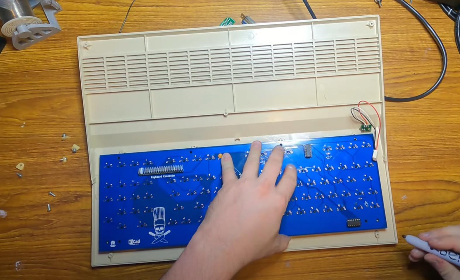
Test fit of the PCB in the case from the video.
Finally, I wanted to test the fit. Which when I did, it seemed like all my holes were out of place, despite me measuring several times. In the video I even went so far as to mark where the new holes should go. But what I marked were where the holes for the bracket should go, not where the holes for the keyboard should go. After the video I went back and placed a blank PCB and made sure the holes were in the right place for the keyboard, and found I needed to make some small tweaks, but nothing that would make rebuilding the PCB a problem.
The 3D printed plate I had made just to check fit was too thick for the prototype to use it, so I’ll be adjusting that and printing a new one. Additionally, I think that’s going to end up being the whole brace unless I find a way to reuse the plate that already exists.
I’m really excited for part 2, but that is a little ways out still. I need to finish the PCB update and the 3D printer plate/bracket designs first!